CRGC130: Ceiling grid for cleanrooms
5.5.2021
130mm thick ceiling grid for use in cleanroom
Due to the increasingly demanding market in which the company Klimaoprema has started working on projects, the R&D department of Klimaoprema was given the task of developing a new type of grid ceiling for use in spaces where strictly controlled air conditions are a must. Said spaces are intended for scientific research, pharmaceutical manufacturing, microelectronic manufacturing and similar work, and the ceiling serves as an element for ensuring a clean space. The main characteristics of the ceiling are permeance and a thickness of 130 mm, which allows the integration of most ceiling elements, as well as cable laying within the overall dimensions of the ceiling. Wiring is performed through grid profiles, with the possibility of connecting the elements inside the panel.The product complies with the following standards:
- Construction Products Act (Official Gazette No. 86/08)
- European Standard for Medical Devices ISO 13485: 2016
- European Standard for Medical Devices ISO 14971: 2019 (Medical devices – Application of risk management to medical devices)
- European Standard for Quality Management ISO 9001: 2015
- European Standard For Cleanrooms ISO 14644-1,4,5,7
Technical characteristics of the CRGC130 ceiling:
- Grid profiles and 1.5 mm thick platinum top; DX51D 200Z
- 1.25 mm thick platinum bottom; DX51D 200Z
- Loadbearing capacity of the ceiling: 2.5 kN/m2
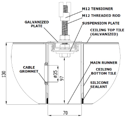
- Total ceiling thickness: 130 mm
- Panel dimension: 1.2x1.2 m
- M12 suspension grid dimension: 1.2x2.4 m
- 2 – 3 mm thick joints
Main advantages of the CRGC130 ceiling:
- Easy and flexible installation
- Standardized parts
- Respective pieces of platinum can be easily removed/changed
- Full integration of lighting modules and wiring into the thickness of the ceiling
- Fully flushed lower visible side of the ceiling, which meets the strict GMP guidelines
- Machine-made openings in platinums of different dimensions
- Installation independent of the walls in the space
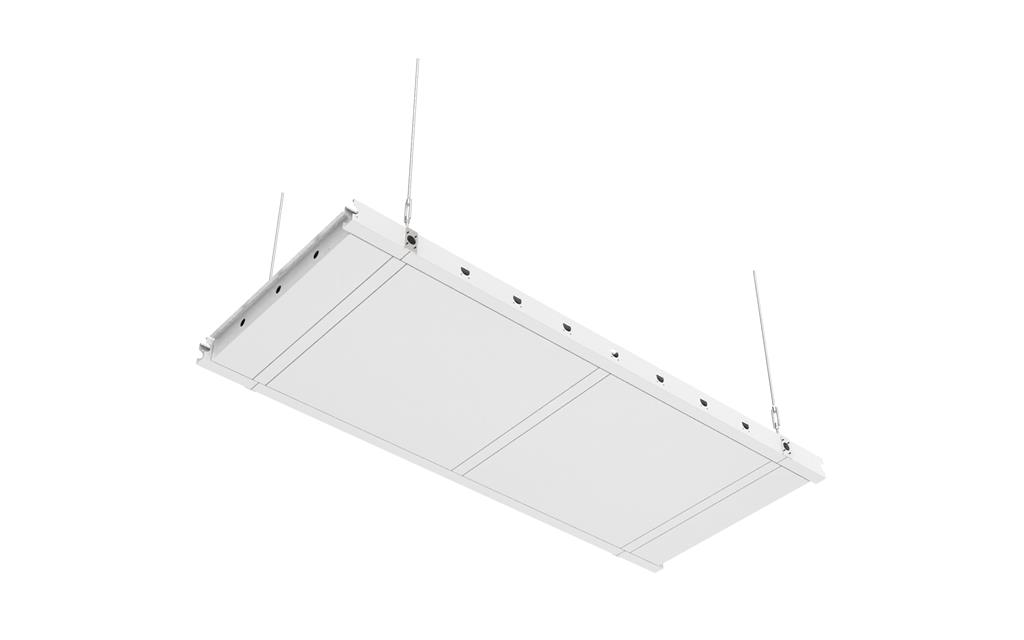
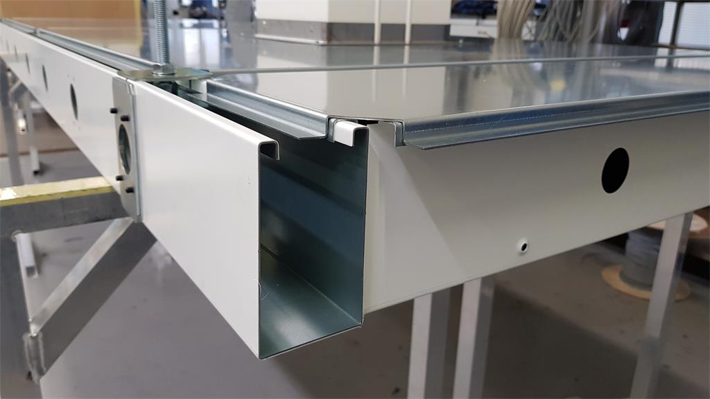
Ceiling segment
Development and production
When constructing the elements of the grid ceiling, special attention was paid to compatibility with other elements of the cleanrooms architecture, fast position planning and simple and standardized installation. The development procedure consists of construction according to the input parameters that the product should meet, prototyping, compatibility testing, loadbearing testing and, if necessary, potential finishing touches.
The production of ceiling elements is automated due to their usually standard nature and the need for fast delivery of large quantities of ceilings. It takes place on an automated production line in the manufacturing plant Nova Gradiška, and includes plasticized bale sheet punching, bending with a brake and palletizing. This significantly speeds up the production process and ensures high repeatability and quality of all manufactured parts. With such a production process, the influence of the operator on the quality of the product is minimized. The stability of the ceiling construction is ensured by the geometry of the elements and the connecting elements. Thus, the need for welding has been eliminated from the production of individual elements, which enables automated production without the need for subsequent surface protection in the form of plasticization.
Testing
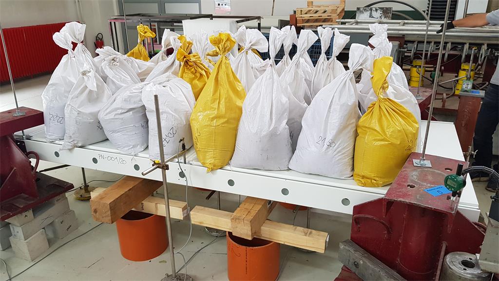
Testing the loadbearing capacity of the ceiling was performed according to the requirements of thee EN 13964: 2014 standard. The test was carried out in the laboratory of the IGH Institute. The test procedure includes loading the ceiling with predefined masses according to the guidelines from the standard.
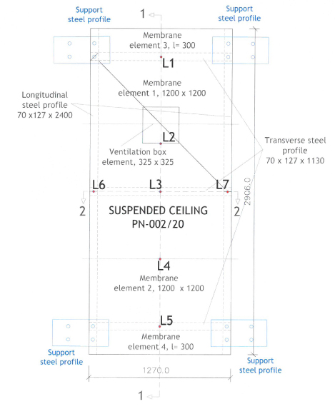
During the test, the test sample was loaded with bags of quartz sand of known mass, evenly distributed over the surface. Sandbags were placed on the top surface of the ceiling. The loadbearing capacity was defined by the manufacturer, and the values were 2.5 Kn/m2, 3 kN/m2 and 5 kN/m2. During the loading procedure, the initial value was 80% of the loadbearing capacity. The load was increased in 5% increments of loadbearing capacity. Load increments were implemented uniformly in less than 60 s. Each load increment was maintained for 600 ± 10 s. The mass of the sandbags required to achieve the total desired loads for all five load increments was calculated in advance. After the load had reached the total target amount corresponding to the loadbearing capacity value, the test sample was unloaded and the residual displacement was measured each time. Displacements during static testing were measured with linear variable differential transformers at seven measuring points which are in accordance with the positions indicated in the figure by the designations L1-L7.
LVDT deflection measuring device layout (L1-L7)
Loadbearing test in the IGH laboratory for testing the mechanical properties of the product
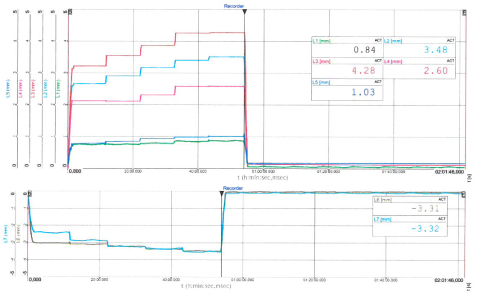
Results of ceiling deflection under a load of 2.5 kN/m2
Design and installation
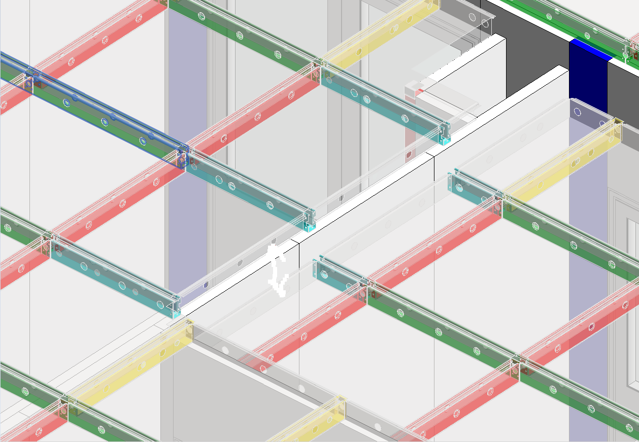
Ceiling design is performed in the Autodesk Revit software package according to the design instructions. In order to make both the design and installation easier, most elements are standardized, and a total of 5 standard profile dimensions are used. When it comes to the production of panels, there is certain flexibility and the panel dimension and the position of the openings in the platinum changes relative to the needs of the project. Ceiling installation is performed according to project documentation, technical drawings and installation instructions.
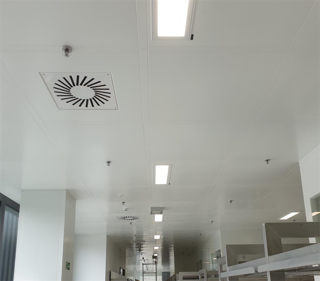
A finished ceiling within the Peregrine project; Lonza